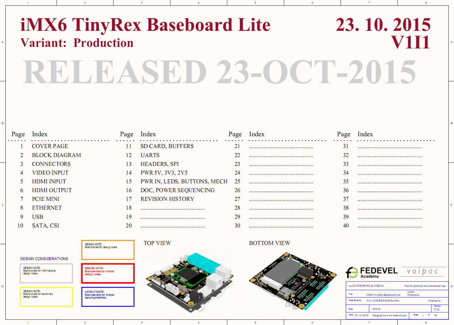
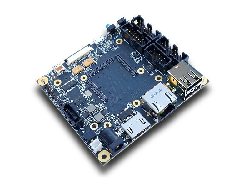
Designed by FEDEVEL Academy
Designed to support the basic peripherals of the i.MX6 TinyRex module.
Status
Available. Purchase iMX6 TinyRex Baseboard Lite from VOIPAC >
iMX6 TinyRex Baseboard Lite specification
- Back panel
- - 1Gb Ethernet
- - HDMI Output with Audio
- - 2x USB (Optional: 1x USB )
- - Power input jack: 3.2-5.5V DC
- Front panel
- - HDMI Micro Input with Audio (e.g. from GoPro camera)
- - MIPI-CSI Camera input (compatible with Raspberry Pi)
- - USB OTG Micro (Optional or Optional Power Input)
- - Micro SD card
- - Buttons: RESET, User Button
- - LEDs: Power LED, User LED
- Side panels
- - 1x SATA
- - 1x UART debug console header (compatible with FTDI cable)
- - Power input / output header
- Bottom
- - 1x PCIE mini card socket (PCIE & USB)
- Headers
- - 4x UART
- - 1x SPI
- - 1x CAN (CMOS)
- - 3x I2C
- - 2x PWM
- - 8x GPIO (can be used for Buttons, LEDs, …)
- On board HDMI video receiver
- On board SPI Flash (up to 128Mbit)
- Four additional holes for heatsink
- Size: 90 x 80 mm (3.55 x 3.15 inch)
Download The Complete iMX6 TinyRex Baseboard Lite Altium Project & Manufacturing Files
Please, Register or Login to download this file
Software
We have done some software work on TinyRex, which you can find below. However, the best is go to VOIPAC TinyRex Wiki, they do a lot of software work to support TinyRex module. In case you would like to learn how to create software for your own baseboard, have a look at software pages created for OpenRex, that will help you.
Schematic
 Download iMX6 TinyRex Baseboard Lite schematic in PDF
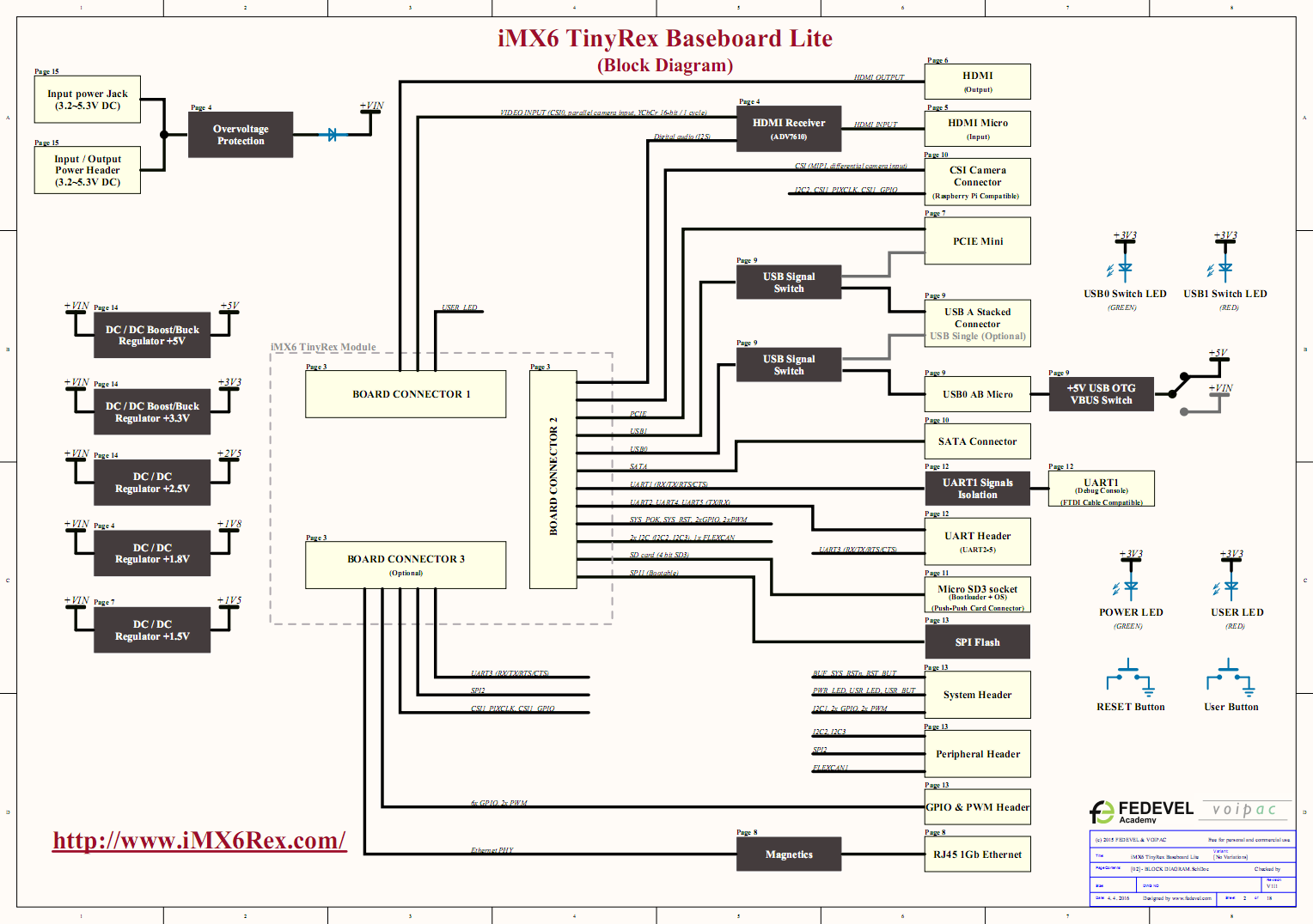
Block Diagram

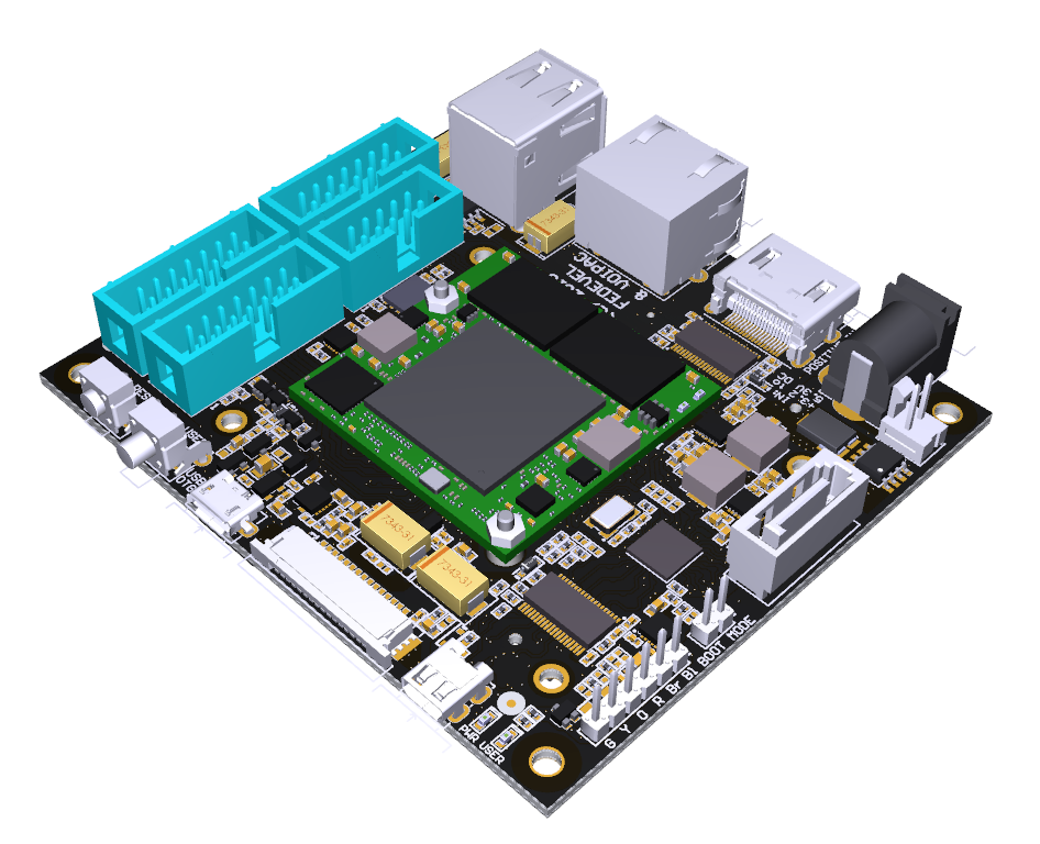
3D PDF Document (use Adobe Reader)
 This is the iMX6 TinyRex Baseboard Lite 3D PDF (use Adobe Reader to open it)
Video
TinyRex HDMI input interface
Project status
| Description | Status | Note | |
| DDR3 | OK | Running memory test for 2 weeks | |
| 1Gb Ethernet (J5) | OK | Running stresapptest with ethernet for 2 weeks | |
| SATA (J9) | OK | File copy test during 3 days | |
| HDMI Output (J6) | OK | Linux boots up to GUI | |
| HDMI Input (J11) | OK | HDMI Output from PC connected to HDMI input and shown by Tiny | |
| PCIE Mini (J13) | OK | Tested with Intel Wifi Card | |
| Micro SD (Slot J15) | OK | Linux boots up from SD | |
| USB OTG (J14) | OK | A firmware uploaded to the module | |
| USB (J4) | OK | USB mouse detected and running ok | |
| Debug Serial Port (J10) | OK | Console output, tested with FTDI cable | |
| Power LED (D4 Green) | OK | Shows the status of power supplies | |
| Reset button (SW1) | OK | The board resets when this button is pressed | |
| User button (SW2) | OK | A small application reads the status correctly | |
| Power Input (J7) | OK | Board boots up ok |
Licence


